Installation
Package Inspection
Before unpacking, check whether the packaging shows any obvious signs of damage. If any damage is found, do not unpack the product; verify the system model and contact the dealer as soon as possible.
After unpacking, check whether each product is intact. If there is any obvious appearance damage, contact the distributor as soon as possible.
Scope of Delivery
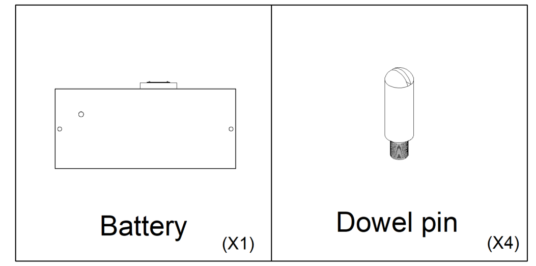
Check the scope of delivery and inspect components to ensure they are present and undamaged.
Contact your distributor if the packed components are incomplete or damaged.
PCS: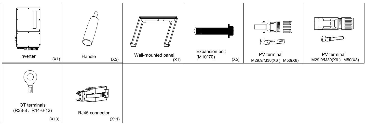
Battery:
HV Box:
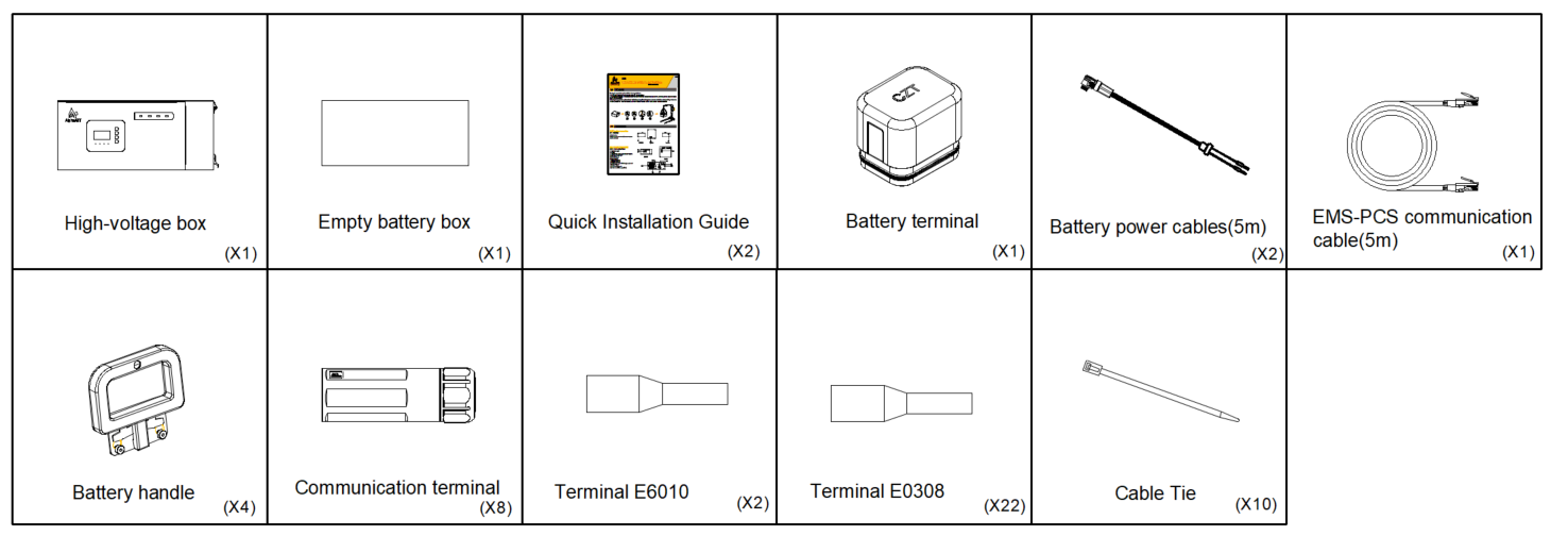
Base:

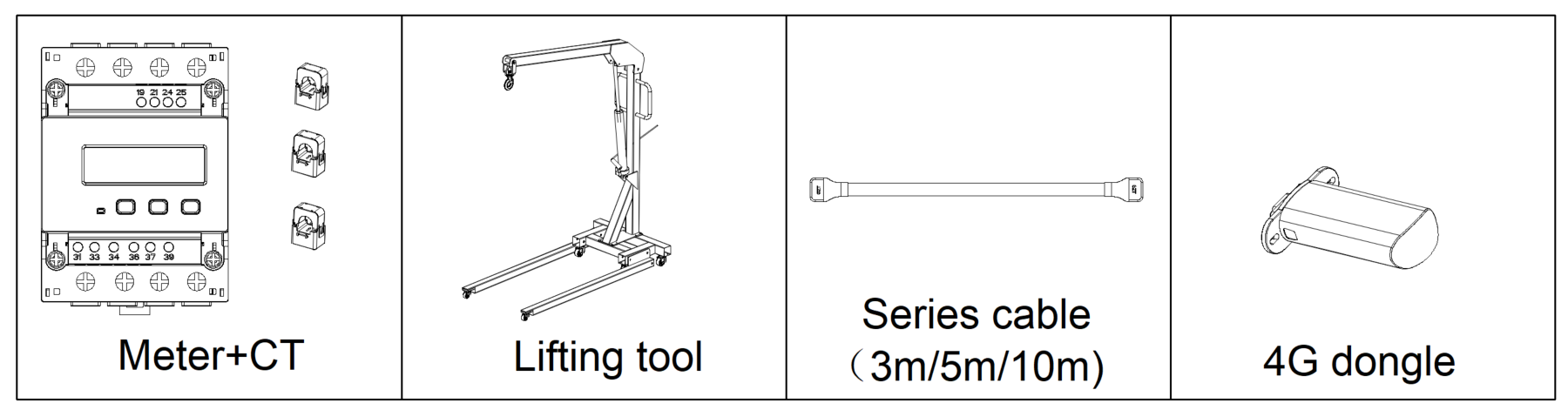
Other accessories:
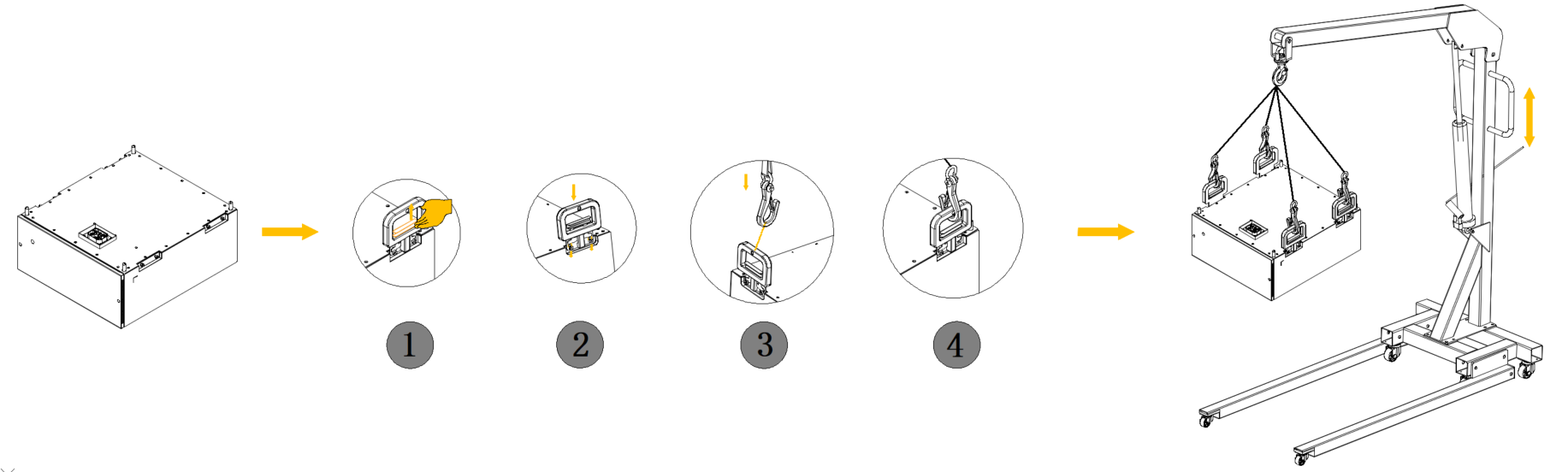
AlphaESS Lifting Tool
You may install the battery either by lifting it with AlphaESS Lifting Tool or without using AlphaESS Lifting Tool. If AlphaESS Lifting Tool is used for installation, follow the steps below:
Product Installation
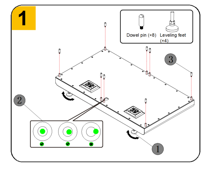
Base Installation
Remove the base from the carton and transport it to the installation site and ensure that the installation site meets the requirements in Section 1.6.
- Install four leveling feet onto the battery base one by one and tighten them fully.
- Level the base according to the spirit level
- After leveling is completed, Install four dowel pins on the base.
Battery Installation
Notice:
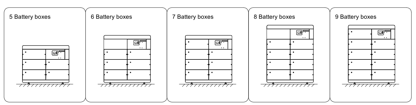
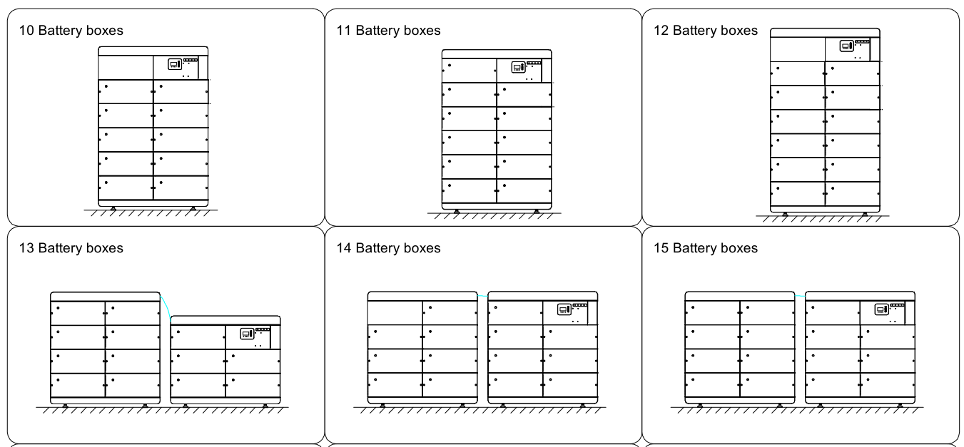
The batteries shall be installed row by row; single-column installation is not allowed. Each base can accommodate a maximum of 12 battery modules and 1 high-voltage box. Installation of more than 12 battery modules is not allowed.
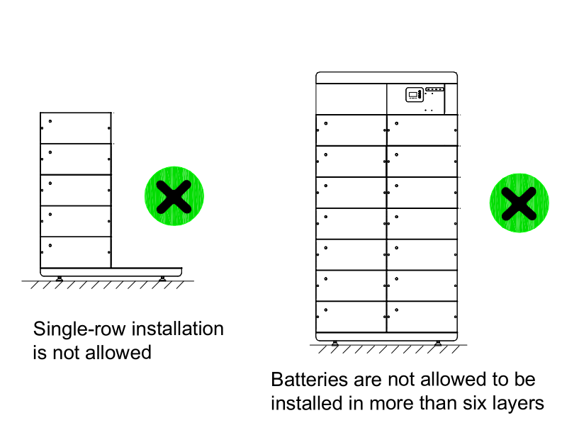
- Open the packaging of the high-voltage box and take out the four handles from the accessories of the high-voltage box.
- Use the handles to remove the battery from the carton, and remove the protective cap from the battery blind-mate connector. At this point, you may choose to install the battery using lifting tools or manually carry and install it.
- Move the battery onto the base. After one battery is installed, take out the positioning post from the battery accessory pack and install it on the battery.
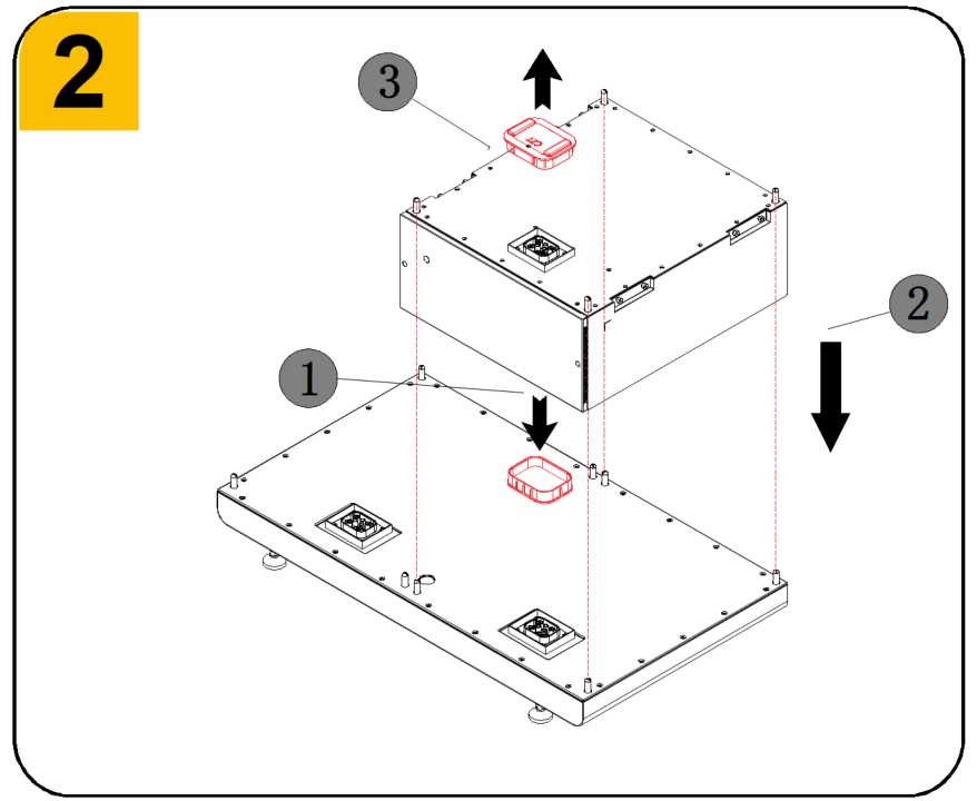
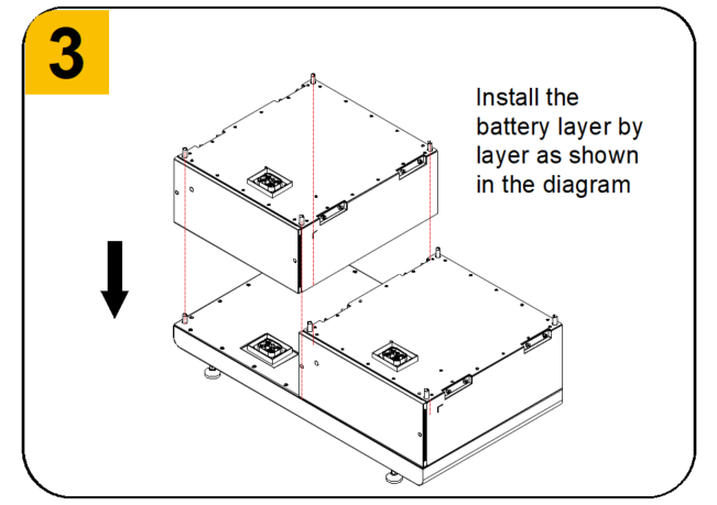
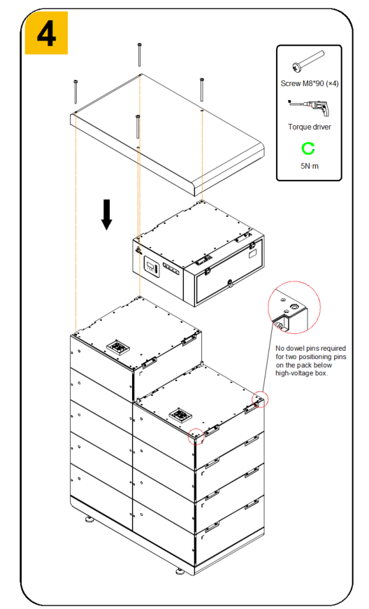
- Install the high-voltage box on the top. (The high-voltage box shall be installed on the right side of the battery). And no dowel pins required for two positioning pins on the pack below high-voltage box.
- Install the cover plate on the top, then take out the screws from the top cover accessory pack and fasten them onto the top cover.
PCS Installation
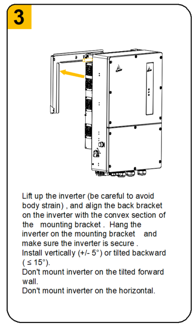
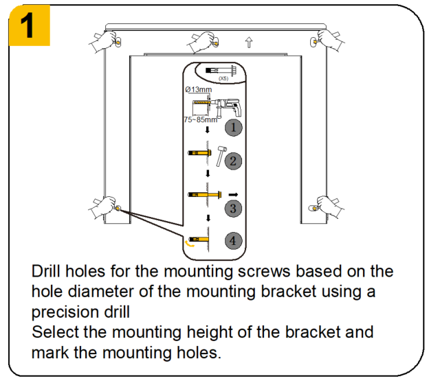
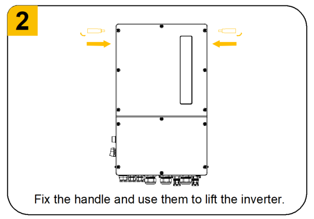
- Install the inverter on a wall or structure capable of bearing its weight.
- The inverter must be installed vertically, with a maximum tilt angle of ±5°. Exceeding this angle may result in reduced output power.
- To avoid overheating, ensure that the airflow around the inverter is not obstructed. Refer to Section 1.6.4 for installation clearance requirements.
- Select the installation height of the bracket and mark the positions of the mounting holes. For brick walls, the hole positions shall match the expansion bolts.
- Lift the inverter, align the bracket on the back of the inverter with the raised surface of the mounting bracket, hang the inverter on the mounting bracket, and ensure that it is securely fastened.
Continuity Test
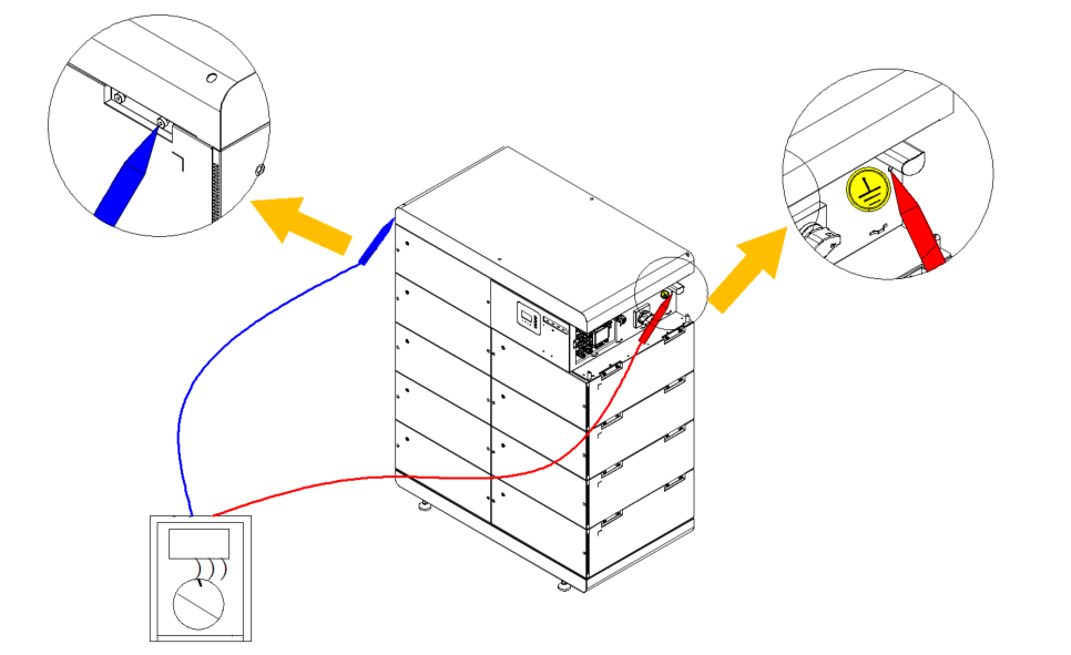
After assembly, use the continuity function of a multimeter to test the connection between the high-voltage box and the last active battery, and ensure good continuity.
Other Battery Installation Layouts
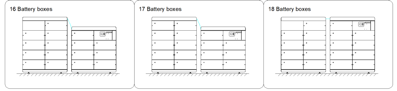
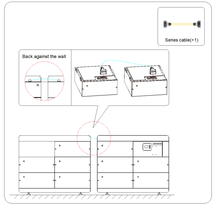
If two bases are used, an inter-cluster cable harness shall be ordered separately. This harness is available in 3 m and 5 m options. The detailed layout and wiring are shown below:
Electrical Connections
Cable Requirements
No. | Cable | Type | Source |
1 | PV power cable | Standard PV cable (recommended type: H1Z2Z2-K)4 ~ 6 mm2 | Purchased by the installer |
2 | AC power(Grid) | Flexible cable 50mm2 | Purchased by the installer |
3 | AC power(Backup) | Flexible cable 20-25 mm2 | Purchased by the installer |
4 | Auxiliary Power Wiring | It is recommended to use 10AWG/6mm² cable with a cable overcurrent of ≥35A and an outer diameter of ≤5.2mm | Purchased by the installer |
5 | PE cable(High-voltage box) | recommend:35mm² | Purchased by the installer |
6 | PE cable(Base) | recommend:35mm² | Purchased by the installer |
7 | PE cable(Inverter) | recommend:35mm² | Purchased by the installer |
8 | DI/DO | Recommend using three four core wires with a diameter of 24AWG/0.2mm ² ~22AWG/0.5mm ² | Purchased by the installer |
System Grounding

Electric Shock Hazard
Before doing electrical connection, please ensure the PV switch & all AC and BAT circuit breakers in the energy storage system are switched OFF and cannot be accidentally or unintentionally reactivated.
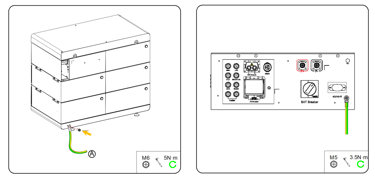
The high-voltage box, base and inverter of the energy storage system are all equipped with grounding terminals. For on-site installation, either the high-voltage box or the base shall be grounded, and the inverter must be grounded.
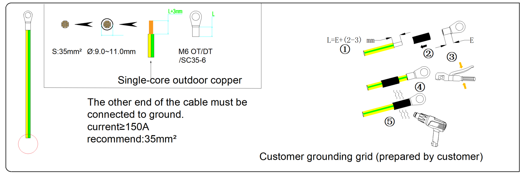
On the battery side, prepare an M6 OT terminal, strip the insulation from the grounding cable, insert the stripped conductor into the barrel of the OT terminal, and crimp it using a crimping tool.
Use a screwdriver with a tightening torque of 5 N·m to connect the grounding terminal to the battery.
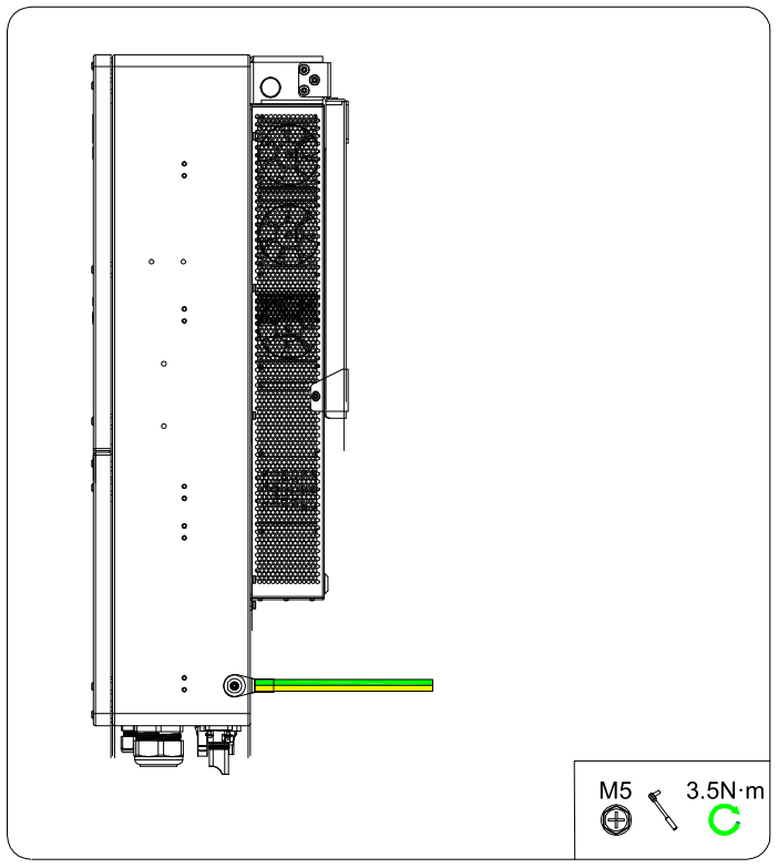
On the inverter side, prepare an M5 OT terminal, strip the insulation from the grounding cable, insert the stripped conductor into the barrel of the OT terminal, and crimp it using a crimping tool.
Use a screwdriver with a tightening torque of 3.5 N·m to connect the grounding terminal to the inverter.
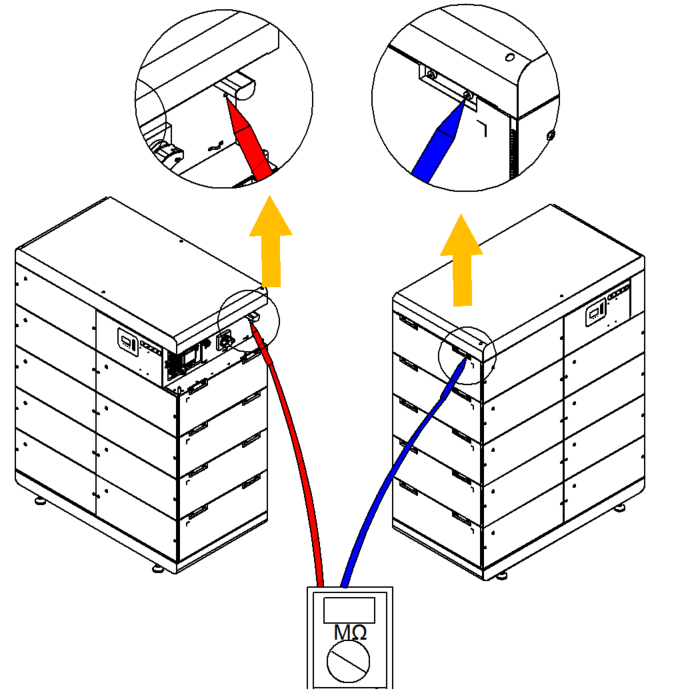
After grounding is completed, the battery grounding shall be checked. Use the positive and negative probes of a multimeter to contact the corresponding positions on the battery and verify whether grounding has been completed successfully.
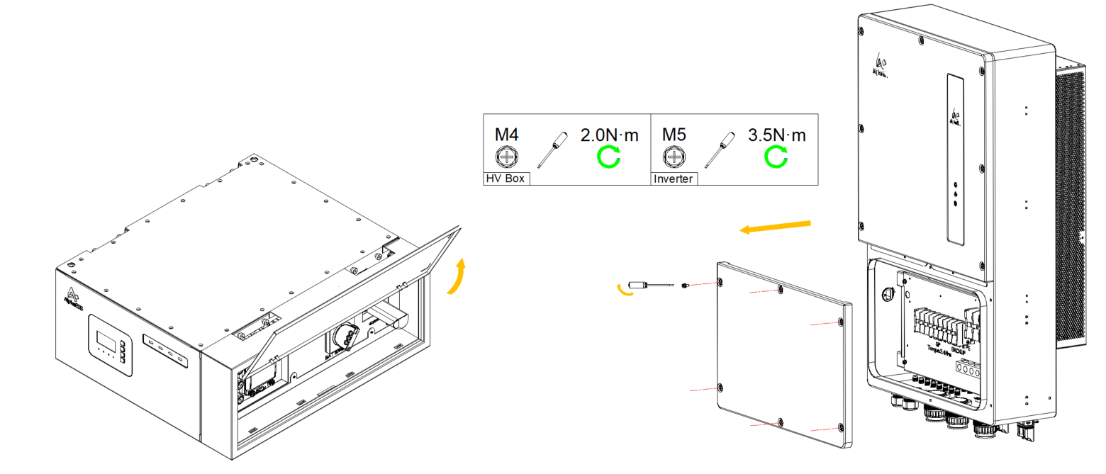
Cover Opening & Removal
Flip open the high-voltage cabinet cover.
Remove the side cover plate of the inverter.
Communication Connection
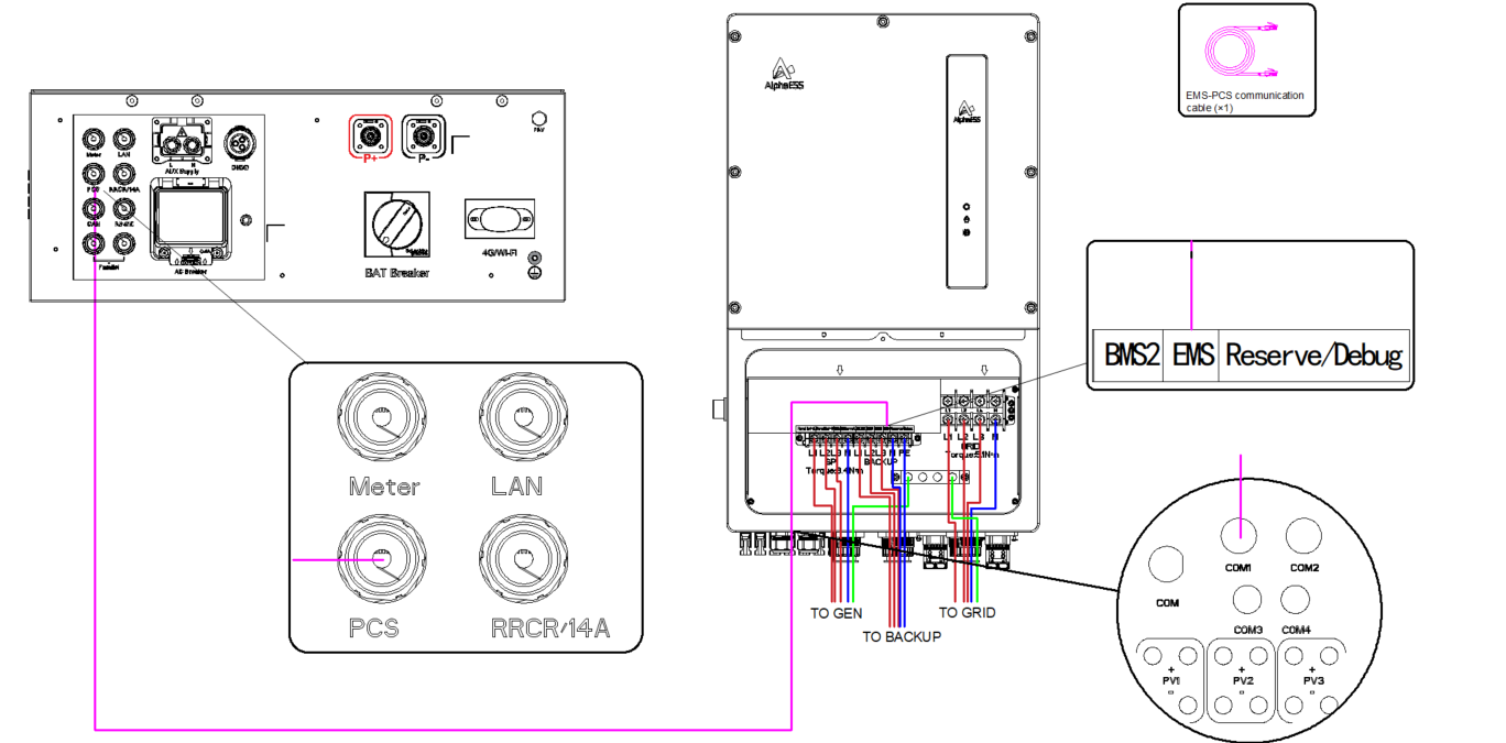
EMS and PCS Communication Connection
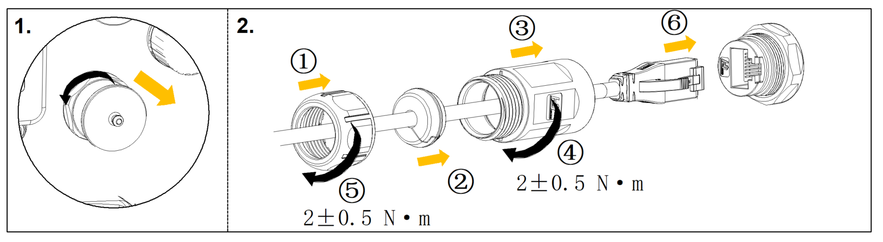
Take out the Ethernet cable from the high-voltage box. Insert one end of the cable through the waterproof terminal into the “PCS” communication terminal of the high-voltage box, and connect the other end through the waterproof terminal of the inverter to the “EMS” terminal of the inverter.
Meter Communication Connection
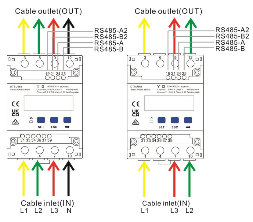
- Connect the grid phases L1/L2/L3/N to terminals 1/4/7/10 of the meter respectively.
- Pass grid phase L1 through the meter CT from the P1 side to the P2 side. Connect the CT secondary terminal S1 to meter terminal 31, and connect CT secondary terminal S2 to meter terminal 33.
- Pass grid phase L2 through the meter CT from the P1 side to the P2 side. Connect the CT secondary terminal S1 to meter terminal 34, and connect CT secondary terminal S2 to meter terminal 36.
- Pass grid phase L3 through the meter CT from the P1 side to the P2 side. Connect the CT secondary terminal S1 to meter terminal 37, and connect CT secondary terminal S2 to meter terminal 39.
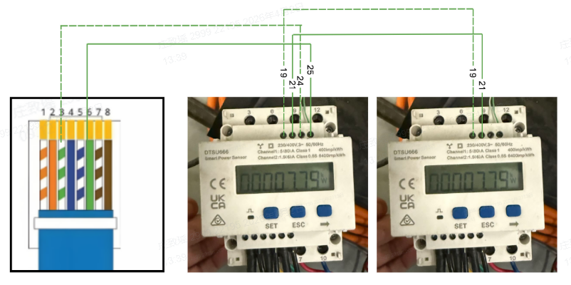
- According to the actual distance to the meter installation location, the customer shall prepare the meter communication cable. Connect one end of the Ethernet cable to the “Meter” port in the high-voltage box according to the procedure in Section 3.5.6. At the other end, connect the green/white wire of the Ethernet cable to communication terminal “24” of the meter, and connect the green wire to terminal “25”.
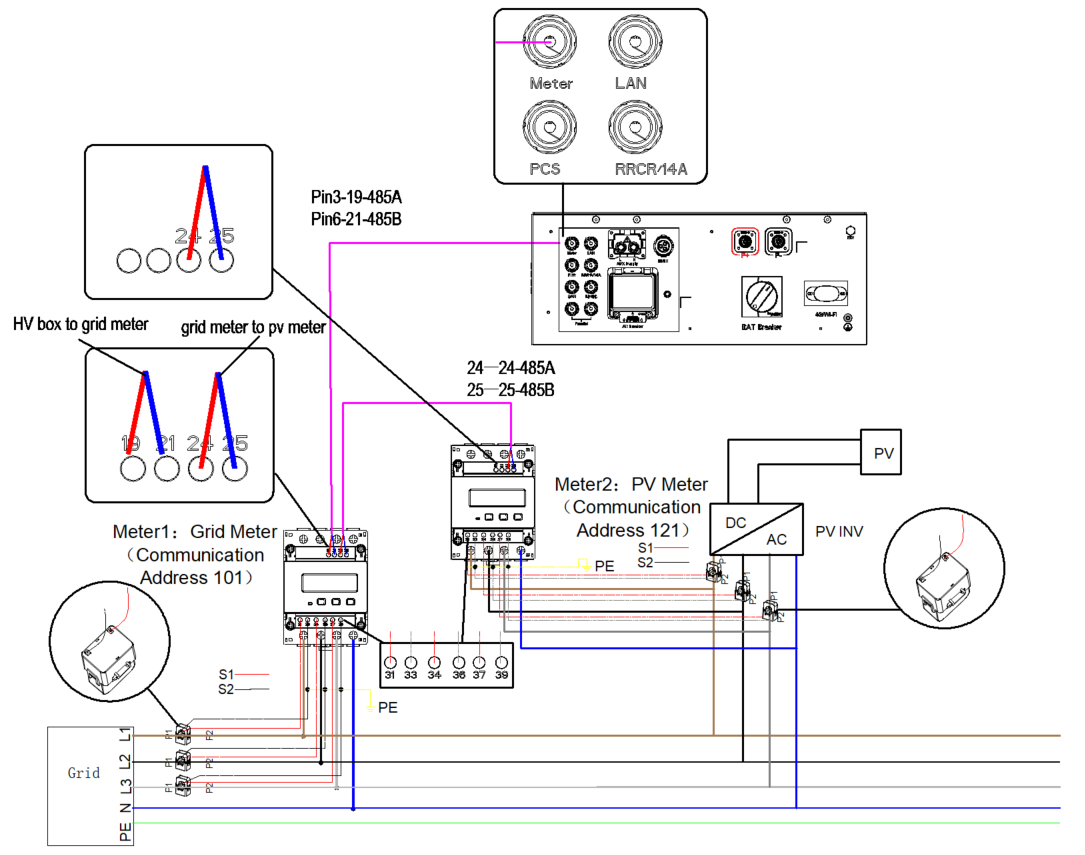
- If a PV meter is used, the two meters shall be connected in series, that is, terminal “19” of the PV meter shall be connected to terminal “19” of the grid meter, and terminal “21” of the PV meter shall be connected to terminal “21” of the grid meter.
- If the direct-connection method is used, ensure the current is less than 50 A. The installation procedure is as follows.
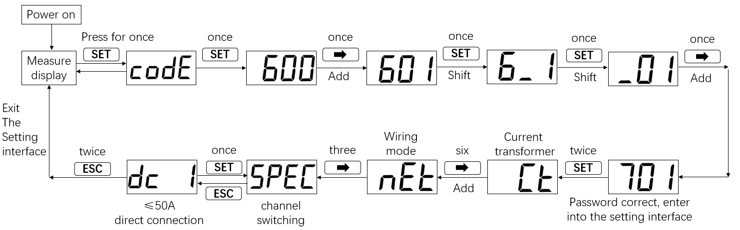
If adopting the direct-connection method, you also need to modify the access mode on the electric meter by following the operations shown in the figure below.
- DTSU666 meter with 6 CT access is supported. Attention: these CTs have narrow measuring ranges and are not allowed for parallel connection.
DI/DO Communication Connection
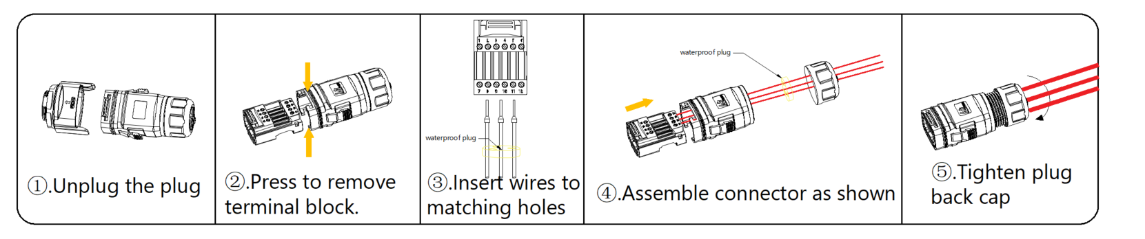
- Press the handles on both sides of the DI/DO port of the high-voltage box, and remove the connector from the high-voltage box.
- As shown in the figure, pull out the wiring terminal.
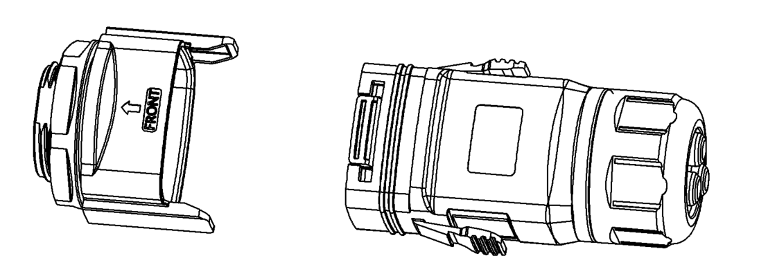
- Loosen the wiring terminal, remove the waterproof terminal, and pass the cable through the terminal.
- Connect the cable harness to the terminal.
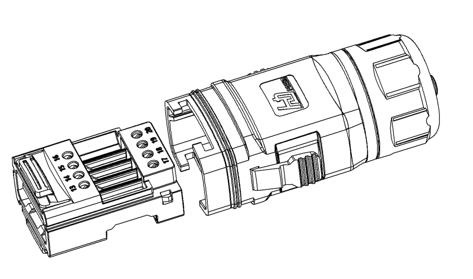
- Insert the wiring terminal back into the connector.
- Tighten the waterproof terminal clockwise.
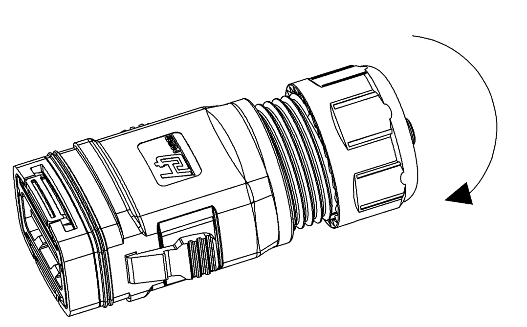
- Insert the connector back into the high-voltage box.
4G Dongle Connection
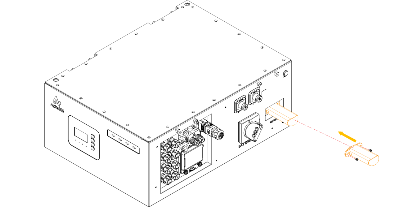
- Remove the right-side cover plate of the high-voltage box.
- Check whether the Wi-Fi dongle is properly installed. If a 4G dongle is required, it shall be ordered separately and used to replace the Wi-Fi dongle.
Note that AlphaESS always recommends a LAN cable connection over the use of a Wi-Fi dongle.
RRCR/14a Connection
If there is an RRCR/14a requirement, complete the wiring as shown in the diagram.
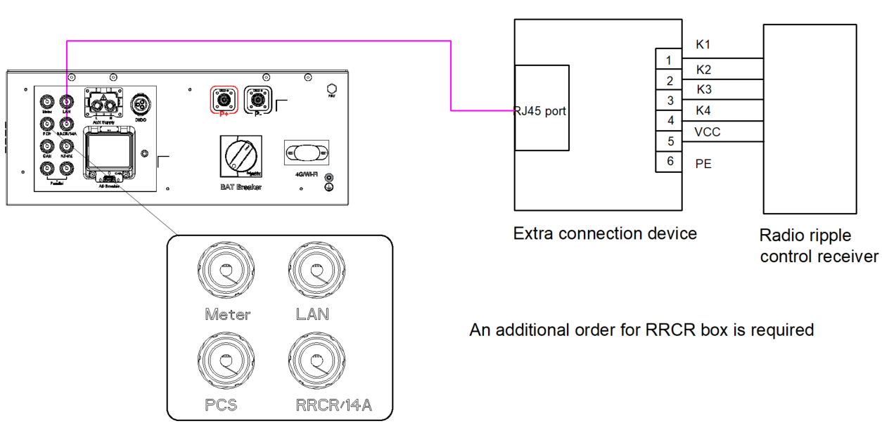
Power connection
PV Connection
Before connecting inverter, please make sure the PV array open circuit voltage is within the limit of the inverter. Before connection , please make sure the polarity of the output voltage of PV array matches the“ DC+ ”and“DC- ”symbols . Please use approved DC cable for PV system .Make sure the photovoltaic cables have no voltage before wiring |
A DC-PV1 switch , complied toAS60947 .3 :2018 , within the inverter, is used as isolating device . Please check below ratings .
DC switch brand | SVRU(TIANJIN) ELECTRICAL EQUIPMENT CO. LTD |
Model | GHX6-55P/8P1100- 45-2-O-F |
PV category | DC-PV2 |
Ue | 1100V |
le | 45A |
Ui | 1500V |
Uimp | 8000V |
lcw | 1500A |
lcm | 2000A |
l ( make)/lc(break) | 180A |
Complied standard | AS 60947 .3:2018 , ASINZS IEC 60947 . 1 :2015 |
- Select a suitable DC cable and strip the wires out by 7±0.5 mm . Please refer to the table below for specific specifications;

- Take the DC terminal out of the accessory bag , turn the screw cap to disassemble it , and take out the waterproof rubber ring;
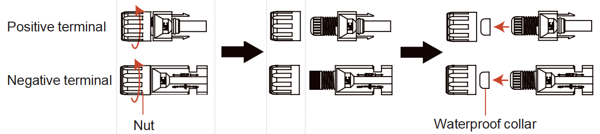
- Pass the stripped DC cable through the nut and waterproof rubber ring;

- Connect the wire part of the DC cable to the metal DC terminal and crimp it with a special DC terminal crimping tool;
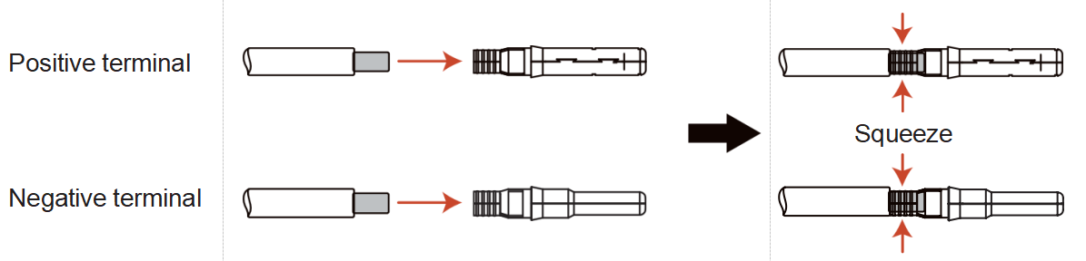
- Insert the crimped DC cable into the DC terminal firmly, then insert the waterproof rubber ring into the DC terminal and tighten the nut;
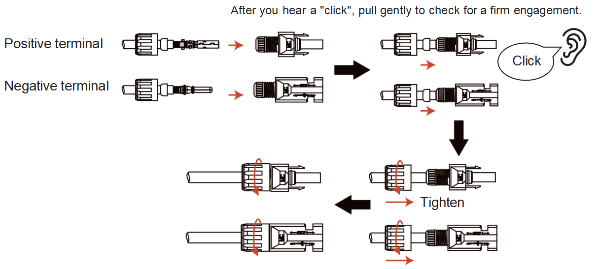
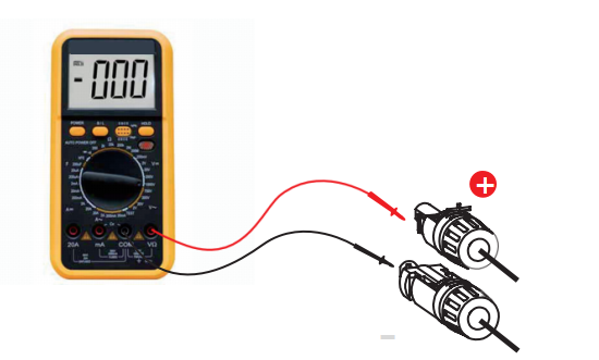
- Measure PV voltage of DC input with multimeter, verify DC input cable polarity;
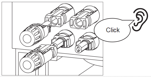
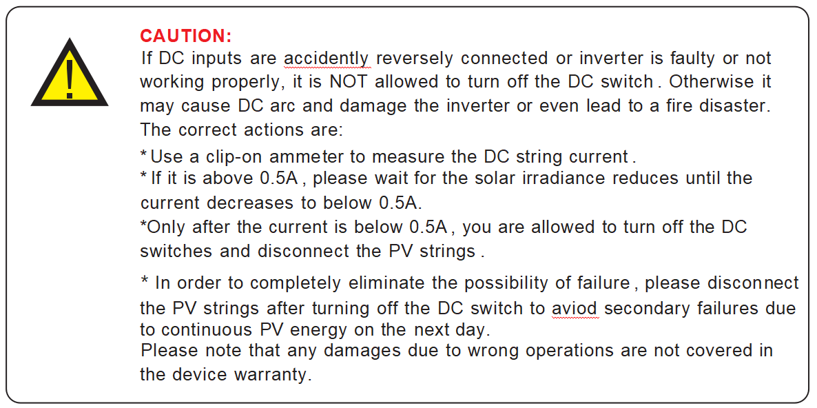
- Connect the wired DC terminal to the inverter as shown in the figure , and a slight "click" is heard to prove the connection is correct;
Battery Power Connection
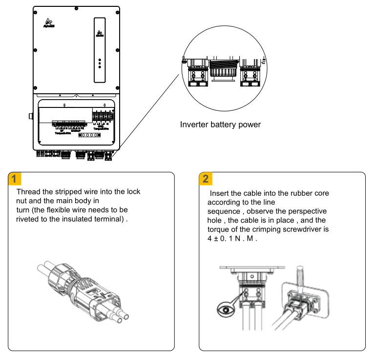
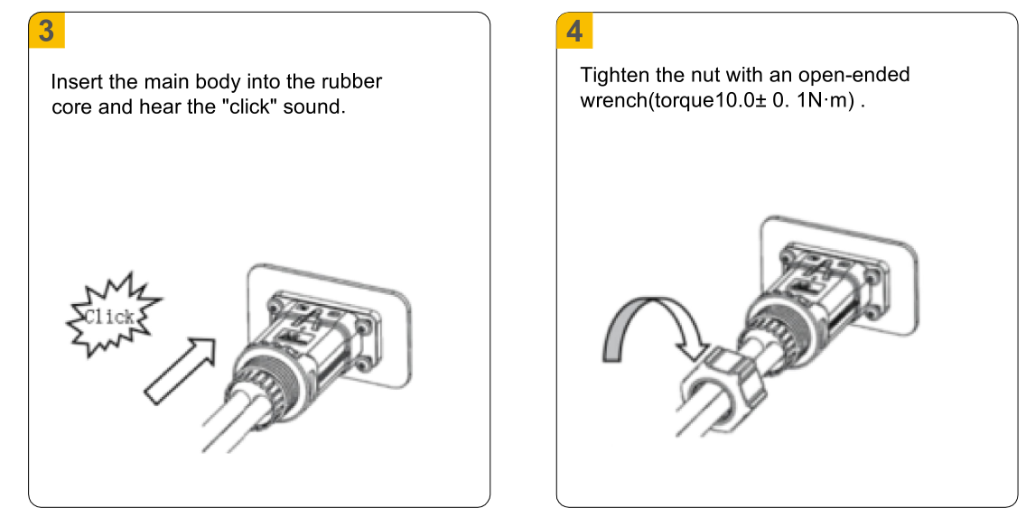
- Take out the battery power cable from the accessory pack of the high-voltage box.
- Insert the end of the cable harness with terminals into the BAT+ and BAT− ports of the high-voltage box.
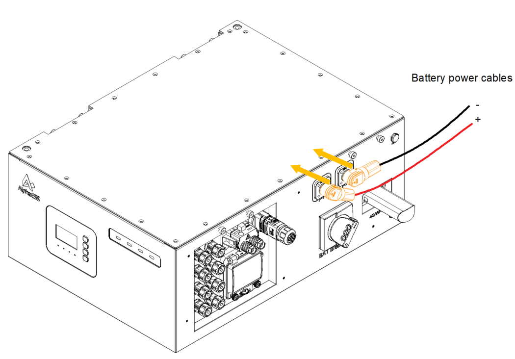
- Remove the soft silicone protection from the other end of the cable harness, and route it through the waterproof terminal of the inverter to connect it to BAT+ and BAT−.
AC Aux Power Connection
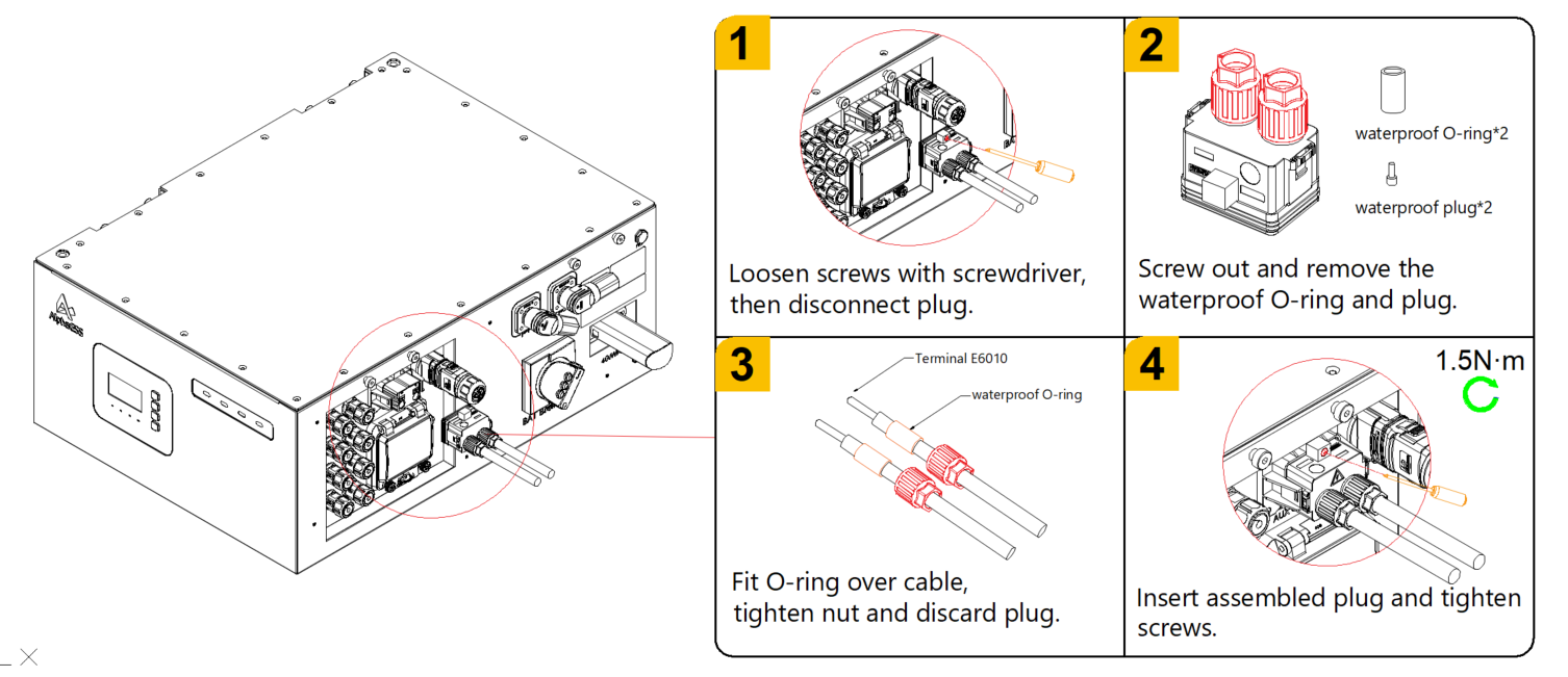
When installing 5 to 9 batteries, use 4mm² power cables. When installing 10 to 18 batteries, use 6mm² power cables.
Wire harness requirements: 12AWG (4mm²) ~ 10AWG (6mm²), with insulation outer diameter of 3.8mm ~ 5.2mm.
Heating strips are supplied by the auxiliary power system. Connection of the auxiliary power supply is mandatory whenever the heating strip is enabled.
If the ambient temperature may drop below 0°C, the auxiliary power cable must be connected; otherwise, keep the auxiliary power switch OFF when the AC auxiliary power supply is not connected.
Grid&Backup&DG Connection
DANGER
Before installing the AC cables , be sure that the OCPDs (breakers) are turned off.
Use a multimeter to verify that the AC voltages are 0Vac before proceeding.
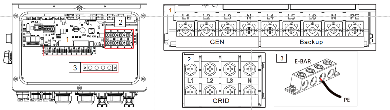
There are three sets of AC output terminals and the installation steps for both are the same . The maximum temperature for connecting AC and battery terminals is 85°C.
Model | Gen port | Backup port | Grid port | Earth Bar |
Wire Size | 3AWG/4AWG | 3AWG/4AWG | 0AWG/ 1AWG | 2 AWG |
Torque | 28.2 N . m | 20.3 N . m | ||
Cable | 20-25 mm2 | 20-25 mm2 | 50mm2 | 33 mm2 |
- Bring the AC cables for the backup loads panel (backup) and the main service panel (grid) into the inverter wire box . The backup loads panel should not be electrically connected to the main service panel.
- Strip 13mm from the ends of each cable . Crimp the R-type connectors onto the ends .
- Remove the terminal bolts , insert them into the connectors , then use a torque wrench to tighten the bolts down .
- Please refer to the terminal labels to connect the AC wires to the correct terminals . Cable Gland are recommended torque for installation is 7-7 .5 N.m . In order to ensure waterproof effect , the operator regularly checks whether the installation is tight.

NOTE:
Now, with the different batches , the inverter after delivery will be subject to the following screen printing sign , compared with the old version , the function of the corresponding terminal will not change , and the way of connecting the
cable will not change and we add the torque data sign for helping installation on site .( In this manual , some diagram contents use the old version sign , but corresponding installation should be based on your machine) .
Requirements for the inverter backup port and Gen port:
- Resistive load & RCD load: single phase Resistive load cannot exceed 100% inverter rated single phase power, the RCD load cannot exceed 60% inverter rated power.
- Motor load: customer should be careful about the impulse power when start the load , ensure the impulse power cannot exceed the overload curve power and time restriction .
- RLC load: total power of load cannot exceed inverter rated power, the instantaneous peak current (peak impulse current) during load switching shall not exceed twice the rated current of the inverter, and the minimum power factor shall not be lower than 0.8.
- Mixed Load: Excluding the RLC load , the motor load and RCD load should be reduced proportionally.
- Isolation transformer: If starting with a transformer, it is necessary to pay attention to the inrush current not exceeding twice the rated current and the inrush power not exceeding the overload curve limit requirements; otherwise , a soft start function needs to be added to the transformer.
Meter Settings
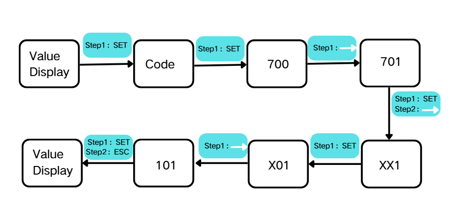
The default meter address is the utility grid meter address. If a PV inverter is added on the Grid side, an additional meter shall be installed, and its address shall be set to 121. The steps for setting the communication address of the meter are as follows:
Parallel Connection Wiring
Communication Wiring
- Parallel harness accessory packs are sold separately; one extra pack is needed per additional paralleled unit.
- Take out the Ethernet cable from the parallel connection harness accessory pack. Connect one end of the cable to the “Parallel” port of one high-voltage box, and connect the other end to the “Parallel” port of the high-voltage box of another system, and so on.

- Take out the other Ethernet cable from the parallel connection harness accessory pack. Connect one end through the “COM” waterproof terminal at the bottom of one inverter to “P-A” or “P-B” of that inverter, and connect the other end to “P-A” or “P-B” of the inverter in another system, and so on.
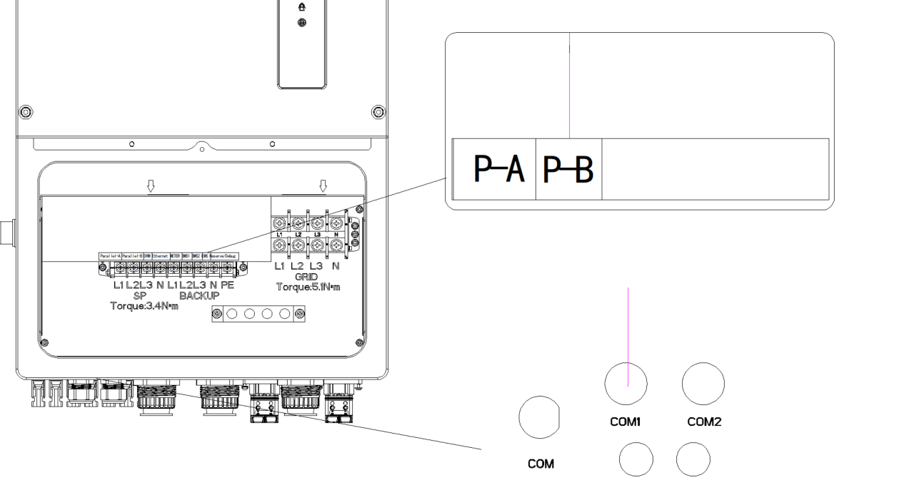
- Take out the terminal resistors from the parallel connection harness pack, and insert them respectively into the unused “Parallel” ports of the first high-voltage box and the last high-voltage box in the parallel system.

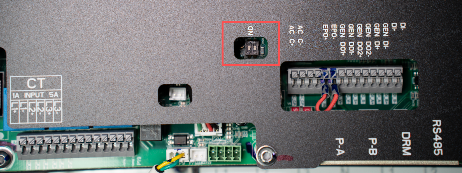
- Finally, set both DIP switches 1 and 2 on the inverters of the master unit and the last slave unit to ON; leave all other devices untouched.
Electrical Wiring
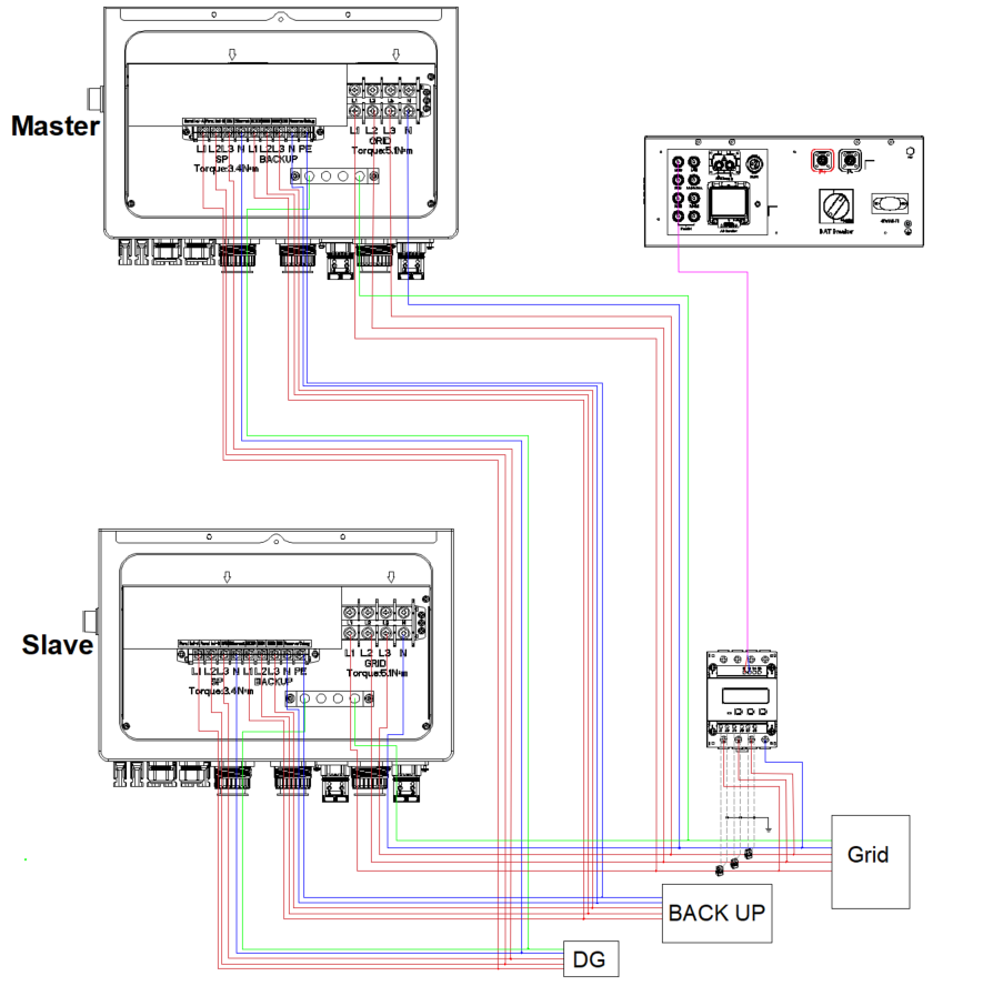
The parallel electrical wiring is as follows:
Equalize the lengths of all branch cables leading to junction points to reduce internal circulating current, optimize control precision and prolong PCS service life.
Commissioning
Cloud Platform Commissioning
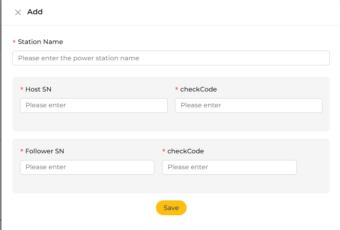
- After completing parallel wiring and power-on, connect the system to the cloud, then add the parallel system via the mobile APP.
- Add a new parallel station on the cloud platform as shown in the figure.

- Enter the information of the parallel station and click Save. The system will automatically complete parallel networking.
On-site Commissioning
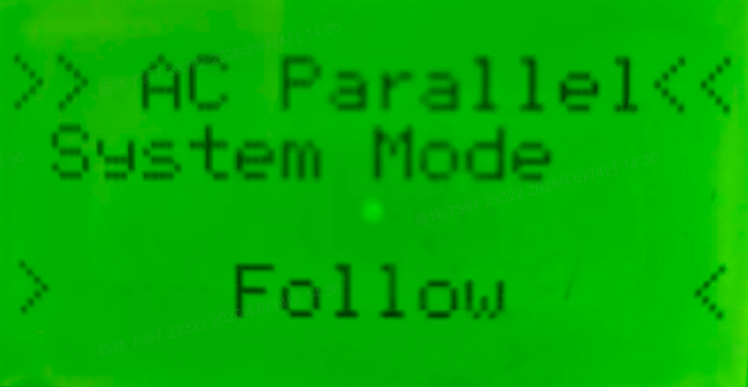
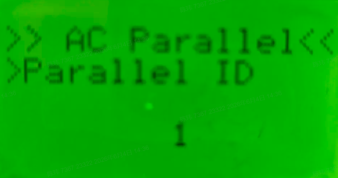
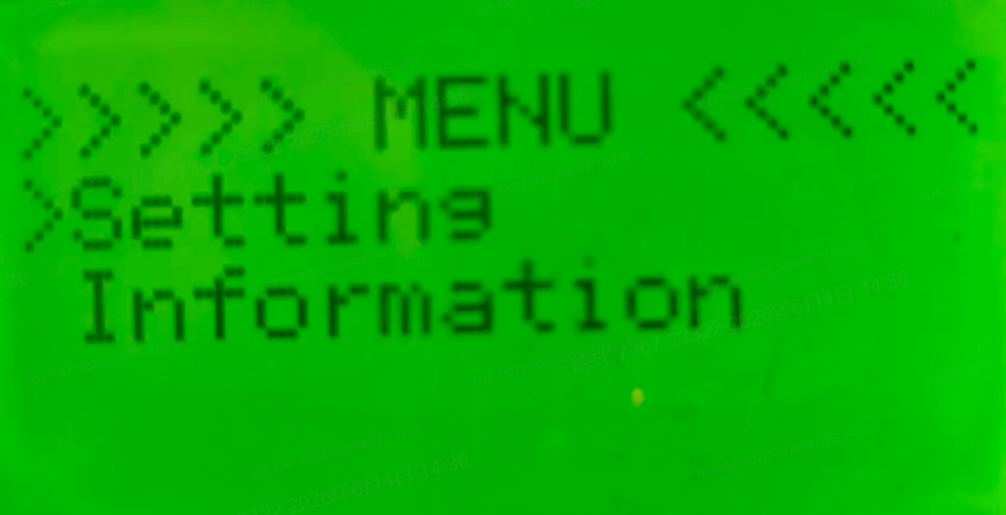
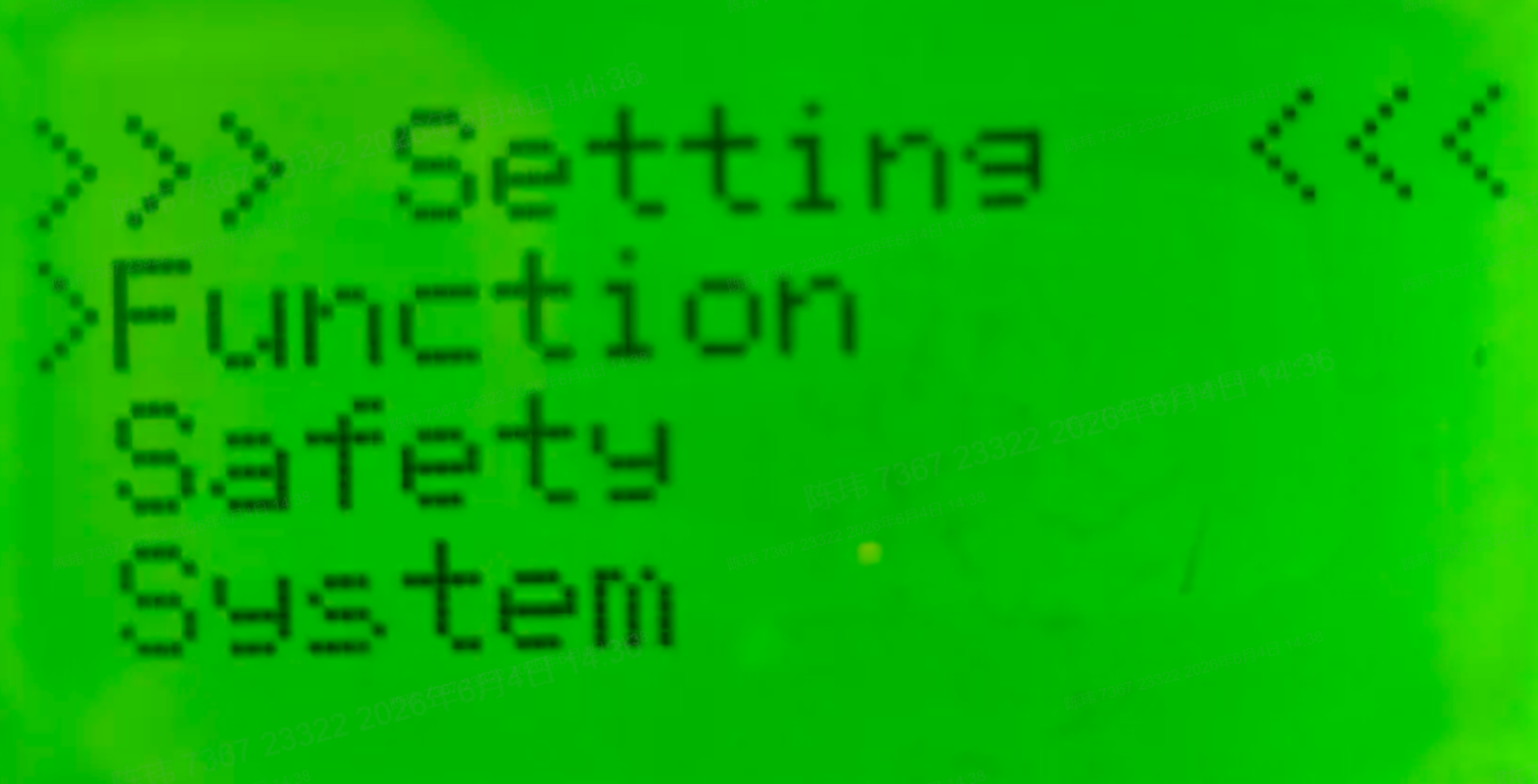
On the LCD of the high voltage box, go to Setting > Function > Parallel > AC Parallel, then set the system mode, total parallel units and parallel ID.
|
|
|
|
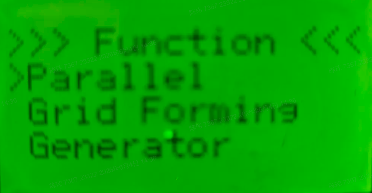
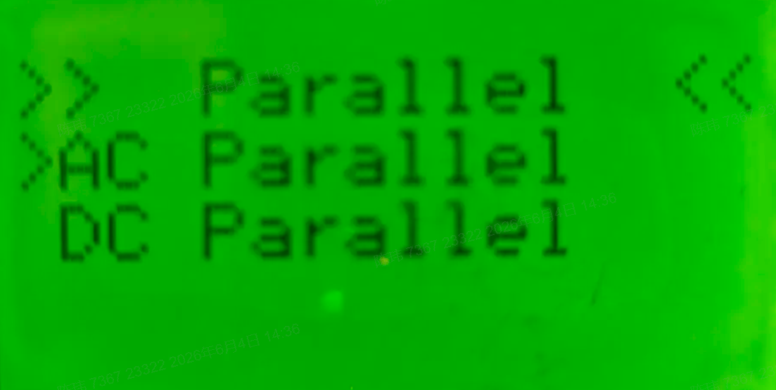
For the master unit: set System Mode to Host. Parallel num refers to the total number of parallel units in the station.
|
|
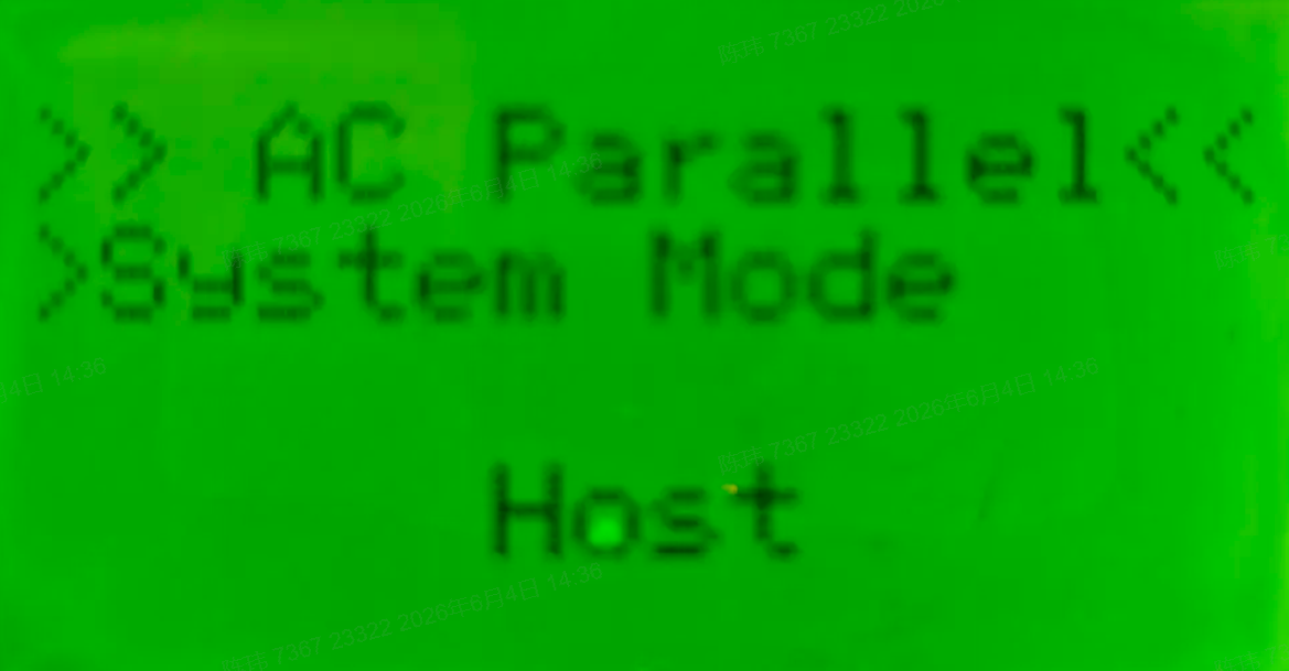
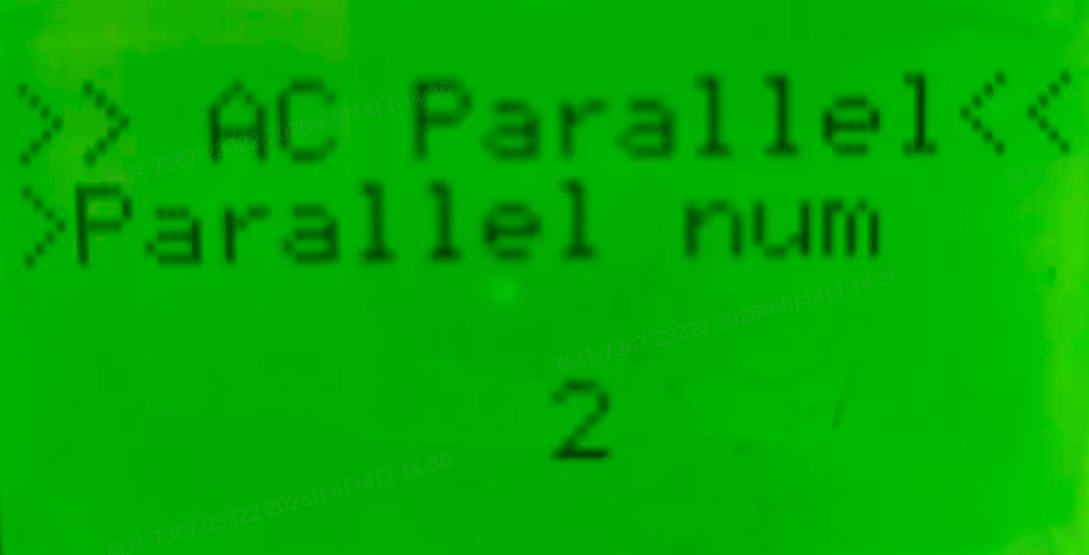
For slave units: set System Mode to Follow. Slave Parallel ID starts from 1.
|
|